-
Notifications
You must be signed in to change notification settings - Fork 5
Examples ultraAstroMorpho2Mesh
ultraAstroMorpho2Mesh reconstructs two-manifold watertight surface mesh models of astroglial cells from their input morphology skeletons that are either stored in SWC or H5 file formats. In this page, we will provide some examples that would demonstrate how to use the application.
This example creates a continuous, optimized, two-manifold and watertight surface mesh of a synthetic astroglial morphology that contains two endfeet. It uses the default packing algorithm (polyline packing), where the interior volume of every polyline in the morphology is voxelized to reconstruct the surface of the final mesh.
ultraAstroMorpho2Mesh \
    --morphology ultraAstroMorpho2Mesh/input/astrocyte-1.h5 \
    --output-directory ultraAstroMorpho2Mesh/example-1 \
    --export-stl-mesh \
    --project-xy --project-zy --project-xz \
    --scaled-resolution --voxels-per-micron 5 \
    --adaptive-optimization --laplacian-iterations 25 \
    --isosurface-technique mc \
--ignore-marching-cubes-mesh --ignore-laplacian-mesh --ignore-optimized-meshThe previous command takes H5 morphology file astrocyte-1.h5 of an astroglial cell that was synthesized based on a recent pipeline1 introduced by the Blue Brain Project.
The output is a corresponding watertight mesh in STL format astrocyte-1.stl (located in the meshes subdirectory).
This mesh can be used directly to create a volumetric (or tetrahedral) mesh to perform a reaction-diffusion simulation in the STEPs simulator. To create this tetrahedral mesh, we used TetGen with the following command:
tetgen -pYqaVBFI ultraAstroMorpho2Mesh/example-1/meshes/astrocyte-1-watertight.stl The resulting volumetric mesh is created in the tetrahedral subdirectory.
A comparison between the input morphology (including the endfeet in green - on the left) and the generated mesh (on the right) is shown in the Figure 1. The inbetween image is a transparency-rendering of the input morphology to reveal its complexity and different components.

Figure 1 Visual comparison between the input morphology and generated mesh of astrocyte-1.
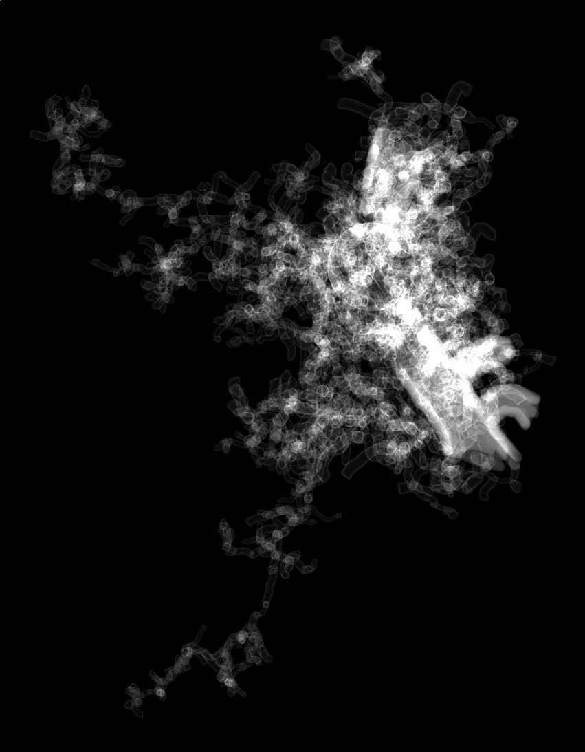
We also used the projection flags --project-xy --project-zy --project-xz to create the three principal projections of the intermediat volume (a rasterization of the input morphology) to validate the structure with the transparent rendering (middle in Figure 1).
The three projections astrocyte-1-projection-xy.ppm, astrocyte-1-projection-yz.ppm and astrocyte-1-projection-xz.ppm are generated in the projections subdirectory. These projections are shown below in Table 1.
| XY | XZ | YZ |
|---|---|---|
 |
 |
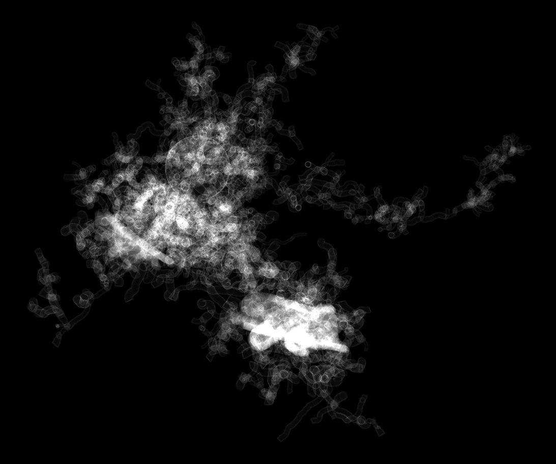 |
Table 1 Orthographic projections of the intermediate volume resulting from rasterizing the input morphology skeleton astrocyte-1.h5. Note that the volume is created using surface rastrization only and this why we can clearly observe the intersections between the different sections in the morphology.
-
This application particularly uses surface voxelization only. It is always advisable to avoid using solid voxelization, i.e. adding the
--solidflag when using ultraAstroMorpho2Mesh. -
The current version of the application must use the marching cubes algorithm for isosurface reconstruction, i.e.
--isosurface-technique mc. The dual marching cubes algorithm does not work. -
Unlike neurons, astrocytes are star-shaped cells with compact sizes, i.e. low spatial extent. Therefore, it is relatively safe to use high values for the Laplacian iterations to maximize smoothing the surface of the resulting meshes. This is why we use 25 iterations in this example
--laplacian-iterations 25.
This example creates a watertight surface mesh of a biologically reconstructed astroglial morphology (stored in SWC format) that does not contain any endfeet patches. This morphology is available from the NeuroMorpho.Org database. Typically, SWC astroglial cells are similar in their structure to neurons; the soma and arborizations are described, but the endfeet are not present. Note that this morphology does not even have an approximate or symbolic description of the soma (as shown in Figure 2, on the left). The command line in this example is similar to the previous one; the only difference is the missing cellular components of the input morphology.
ultraAstroMorpho2Mesh \
    --morphology ultraAstroMorpho2Mesh/input/astrocyte-2.swc \
    --output-directory ultraAstroMorpho2Mesh/example-2 \
    --export-stl-mesh \
    --project-xy --project-zy --project-xz \
    --scaled-resolution --voxels-per-micron 15 \
    --adaptive-optimization --laplacian-iterations 25 \
    --isosurface-technique mc \
    --ignore-marching-cubes-mesh --ignore-laplacian-mesh --ignore-optimized-mesh
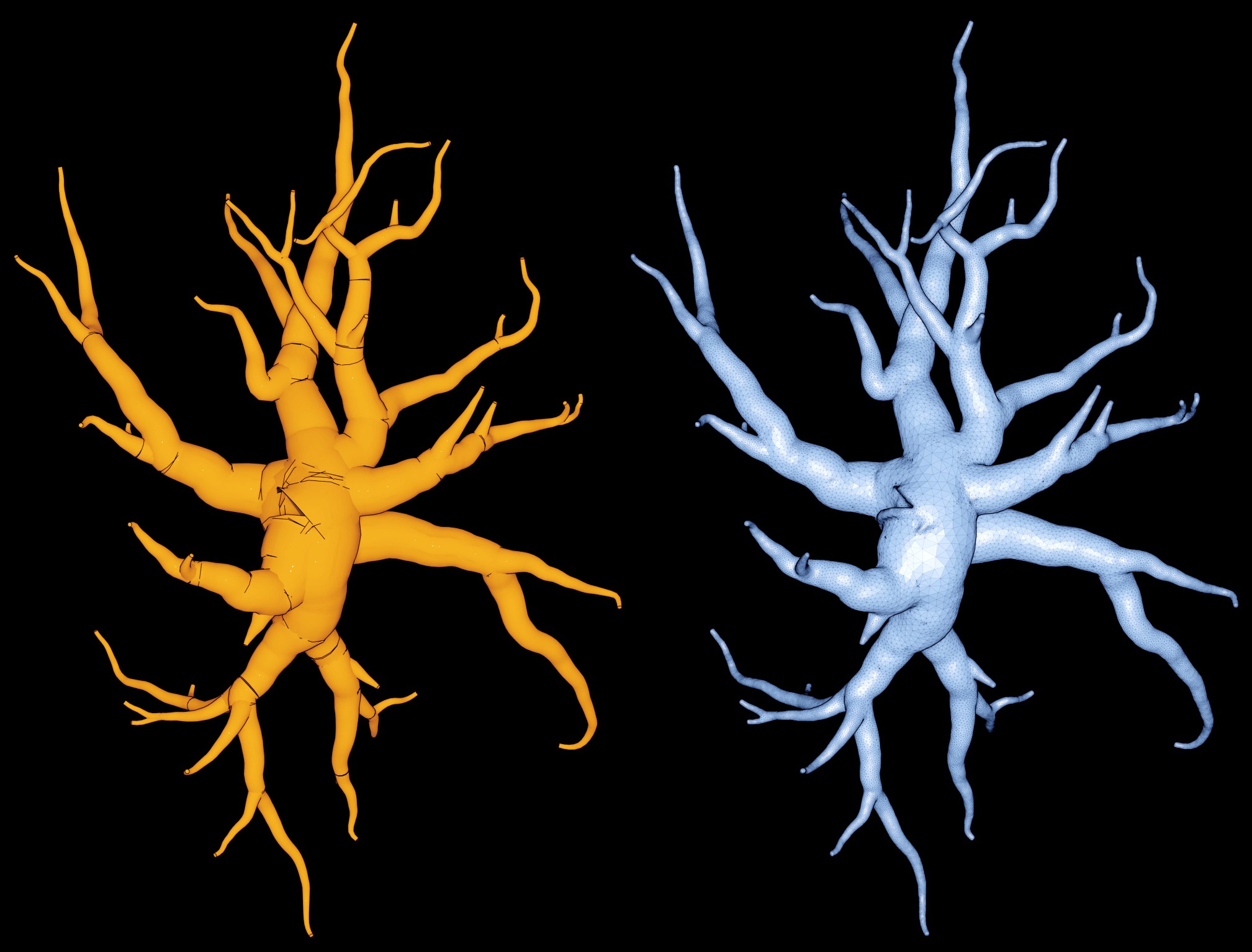
Figure 2 Visual comparison between the input morphology and generated mesh of astrocyte-2.
Note that the input morphology (in SWC format) does not have any endfeet, nor a symbolic sphere representing the soma.
The missing soma caused a sharp edge in the center of the generated mesh (see Figure 3 ), nevertheless the mesh is watertight and its surface is continuous and does not contain any holes or gaps.
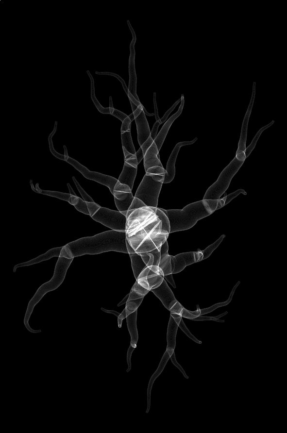
| XY | XZ | YZ |
|---|---|---|
 |
 |
 |
Table 2 Orthographic projections of the intermediate volumes used to rasterize the input morphology astrocyte-2.swc. This example used the polyline packing algorithm to rasterize the input morphology into the volume grid, and this is why we can obviously notice the intersections between the different sections in the morphology.
- The missing soma caused a sharp edge in the center of the generated mesh (Figure 3 ), nevertheless the mesh is watertight and its surface is continuous and does not contain any holes or gaps. This artifact is resolved using other packing algorithms as shown in Examples 3 and 4.


Figure 3 The polyline packing algorithm is not well suited to mesh astrocytes (or neurons) with missing soma description.
This example uses an effective packing algorithm that is much more robust than the default polyline algorithm used in the previous example. This packing technique allows to reconstruct a fully smooth and continuous surface around the somatic region even if the soma description was missing in the morphology file, where this has been the case in astrocyte-2.swc as shown earlier in Figure 2.
The only difference between the command line in the previous example and this one is the application of the polylines with sphere packing algoritm using the following argument --packing-algorithm polylines-with-spheres.
ultraAstroMorpho2Mesh \
    --morphology ultraAstroMorpho2Mesh/input/astrocyte-2.swc \
    --output-directory ultraAstroMorpho2Mesh/example-3 \
    --export-stl-mesh \
    --project-xy --project-zy --project-xz \
    --scaled-resolution --voxels-per-micron 15 \
    --adaptive-optimization --laplacian-iterations 25 \
    --isosurface-technique mc \
    --ignore-marching-cubes-mesh --ignore-laplacian-mesh --ignore-optimized-mesh \
--packing-algorithm polylines-with-spheresThe same SWC astrocyte morphology used in the previous algorithm astrocyte-2.swc is used in this example. The resulting mesh (shown in Figure 4) is generated to the meshes directory.

Figure 4 Visual comparison between the input morphology and generated mesh of astrocyte-2 using the polyline and spheres packing algorithm.
Moreover, the orthographic projections (in Table 3) are generated to the projections subdirectory.
| XY | XZ | YZ |
|---|---|---|
 |
 |
 |
Table 3 Orthographic projections of the intermediate volumes used to rasterize the input morphology astrocyte-2.swc. This example used the polyline with spheres packing algorithm to rasterize the input morphology into the volume grid, and this is why we can obviously notice the rasterized spheress along the junctions between the different sections.
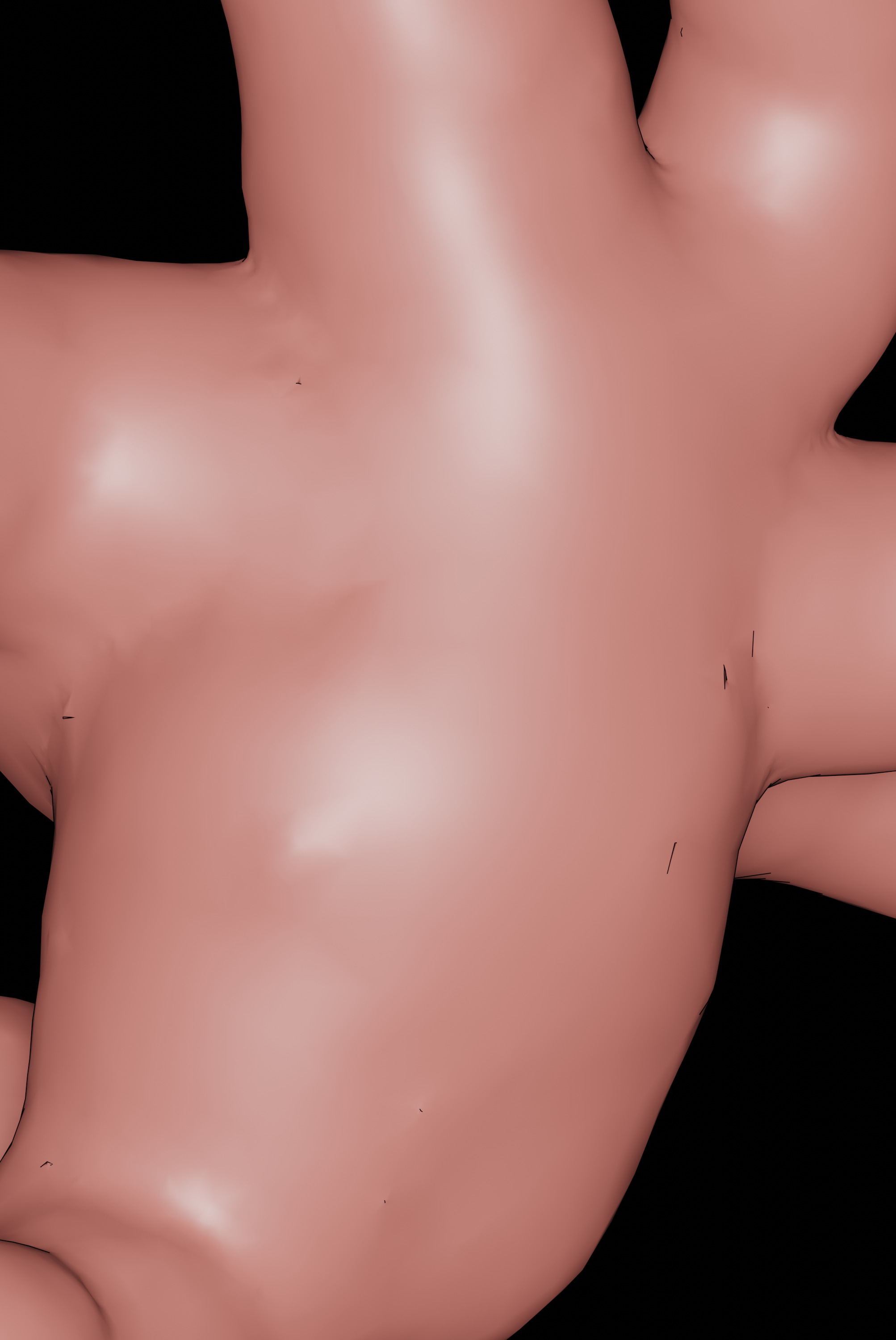
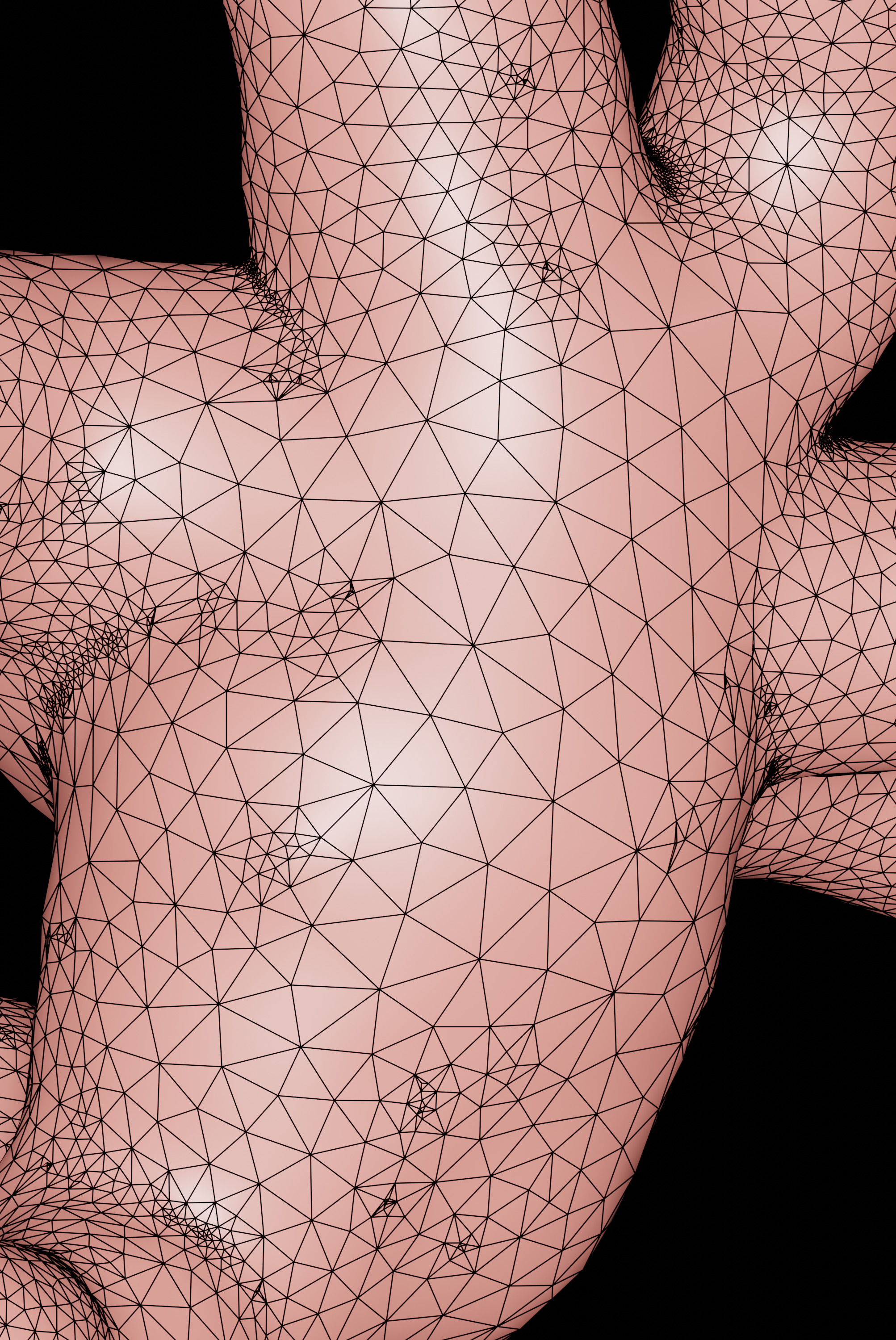
Figure 5 The polyline with sphere packing algorithm is capable of reconstructing a continuous surface mesh with no sharp edges, unlike the polyline packing algorithm (shown in Figure 3).
This example uses another effective packing algorithm that is also more robust and efficient than the default polyline algorithm used in Example 2. This packing technique is based on signed distance field (SDF); it allows to reconstruct a fully smooth and continuous surface around the somatic region even if the soma description was missing in the morphology file.
The only difference between the command line in the previous example and this one is the application of the SDF packing algoritm using the following argument --packing-algorithm sdf.
ultraAstroMorpho2Mesh \
    --morphology ultraAstroMorpho2Mesh/input/astrocyte-2.swc \
    --output-directory ultraAstroMorpho2Mesh/example-4 \
    --export-stl-mesh \
    --project-xy --project-zy --project-xz \
    --scaled-resolution --voxels-per-micron 15 \
    --adaptive-optimization --laplacian-iterations 25 \
    --isosurface-technique mc \
    --ignore-marching-cubes-mesh --ignore-laplacian-mesh --ignore-optimized-mesh \
--packing-algorithm sdfThe same SWC astrocyte morphology used in Examples 2 and 3 is used in this example. The resulting mesh (shown in Figure 6) is generated to the meshes directory.

Figure 6
Visual comparison between the input morphology and generated mesh of astrocyte-2 using the SDF packing algorithm.
| XY | XZ | YZ |
|---|---|---|
 |
 |
 |
Table 4 Orthographic projections of the intermediate volumes used to rasterize the input morphology astrocyte-2.swc. This example used the SDF packing algorithm to rasterize the input morphology into the volume grid.
-
The SDF packing algorithm is relatively faster than the other packing techniques and is recommended to use when the morphology skeleton is incomplete.
-
The projections in Table 4 did not use solid voxelization. It is only the effect of using SDF.
- ZISIS, Eleftherios, KELLER, Daniel, KANARI, Lida, et al. Digital reconstruction of the neuro-glia-vascular architecture. Cerebral Cortex, 2021, vol. 31, no 12, p. 5686-5703.