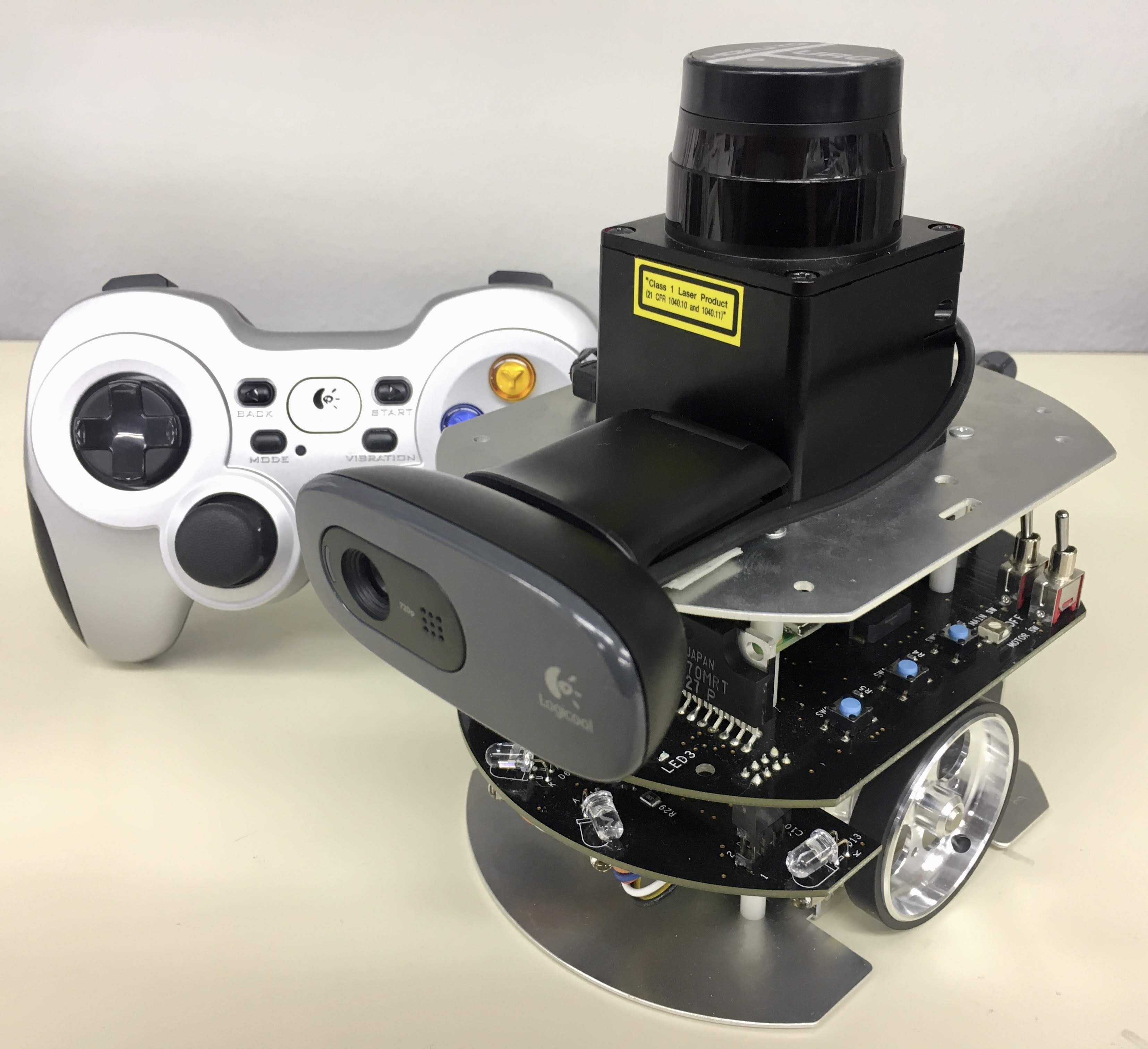
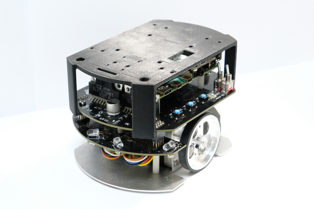
ROS 2 examples for Raspberry Pi Mouse.
ROS1 examples is here.
To run on Gazebo, click here.
- Raspberry Pi Mouse
- https://rt-net.jp/products/raspberrypimousev3/
- Linux OS
- Ubuntu server 24.04
- Device Driver
- ROS
- Raspberry Pi Mouse ROS 2 package
- Remote Computer (Optional)
- ROS
- Raspberry Pi Mouse ROS 2 package
$ cd ~/ros2_ws/src
# Clone package
$ git clone -b $ROS_DISTRO https://github.com/rt-net/raspimouse_ros2_examples.git

# Install dependencies
$ rosdep install -r -y --from-paths . --ignore-src

# Build & Install
$ cd ~/ros2_ws
$ colcon build --symlink-install
$ source ~/ros2_ws/install/setup.bashThis repository is licensed under the Apache 2.0, see LICENSE for details.
This is an example to use joystick controller to control a Raspberry Pi Mouse.
- Joystick Controller
Launch nodes with the following command:
# Use F710
$ ros2 launch raspimouse_ros2_examples teleop_joy.launch.py joydev:="/dev/input/js0" joyconfig:=f710 mouse:=true

# Use DUALSHOCK 3
$ ros2 launch raspimouse_ros2_examples teleop_joy.launch.py joydev:="/dev/input/js0" joyconfig:=dualshock3 mouse:=true

# Control from remote computer
## on RaspberryPiMouse
$ ros2 run raspimouse raspimouse
## on remote computer
$ ros2 launch raspimouse_ros2_examples teleop_joy.launch.py mouse:=false
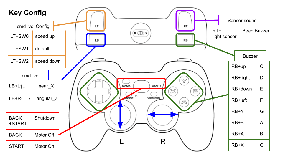
This picture shows the default key configuration.
To use Logicool Wireless Gamepad F710, set the input mode to D (DirectInput Mode).
Key assignments can be edited with key numbers in ./config/joy_f710.yml or ./config/joy_dualshock3.yml.
button_shutdown_1       : 8
button_shutdown_2       : 9

button_motor_off        : 8
button_motor_on         : 9

button_cmd_enable : 4This is an example to use RGB camera images and OpenCV library for object tracking.
- Web camera
- Camera mount
- Orange ball(Optional)
- Software
- OpenCV
- v4l-utils
Install a camera mount and a web camera to Raspberry Pi Mouse, then connect the camera to the Raspberry Pi.
Turn off automatic adjustment parameters of a camera (auto focus, auto while balance, etc.) with the following command:
$ cd ~/ros2_ws/src/raspimouse_ros2_examples/config
$ ./configure_camera.bash
Then, launch nodes with the following command:
$ ros2 launch raspimouse_ros2_examples object_tracking.launch.py video_device:=/dev/video0This sample publishes two topics: camera/color/image_raw for the camera image and result_image for the object detection image.
These images can be viewed with RViz
or rqt_image_view.
Viewing an image may cause the node to behave unstable and not publish cmd_vel or image topics.
Edit ./src/object_tracking_component.cpp
to change a color of tracking target.
If the object detection accuracy is poor, adjust the camera exposure and parameters in the function
void Tracker::tracking(const cv::Mat & input_frame, cv::Mat & result_frame)
{
  cv::inRange(hsv, cv::Scalar(9, 100, 100), cv::Scalar(29, 255, 255), extracted_bin);  // Orange
  // cv::inRange(hsv, cv::Scalar(60, 100, 100), cv::Scalar(80, 255, 255), extracted_bin);  // Green
// cv::inRange(hsv, cv::Scalar(100, 100, 100), cv::Scalar(120, 255, 255), extracted_bin); // BlueThis is an example for line following.
- Line following sensor
- Field and lines for following (Optional)
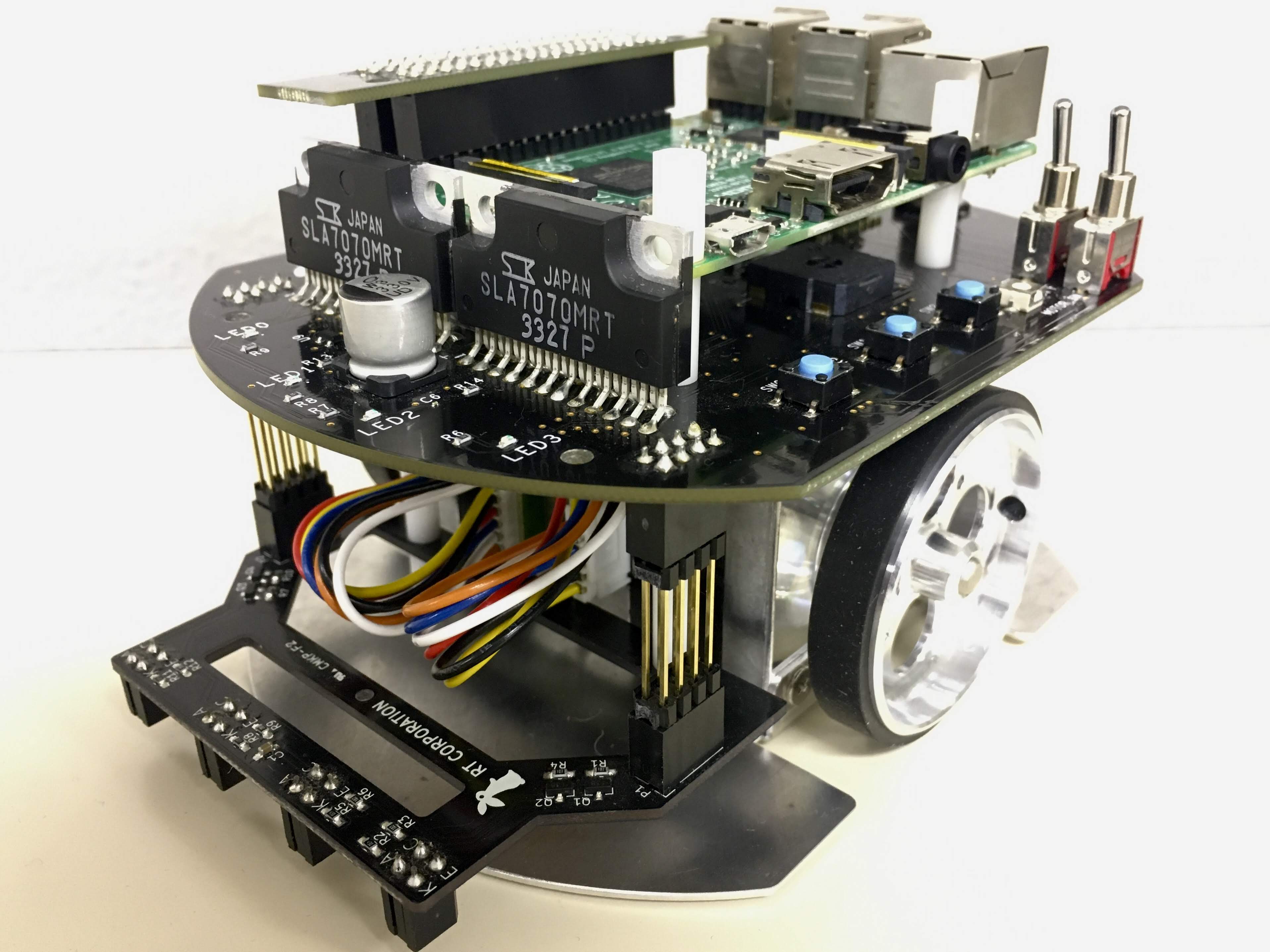
Install a line following sensor unit to Raspberry Pi Mouse.
Launch nodes with the following command:
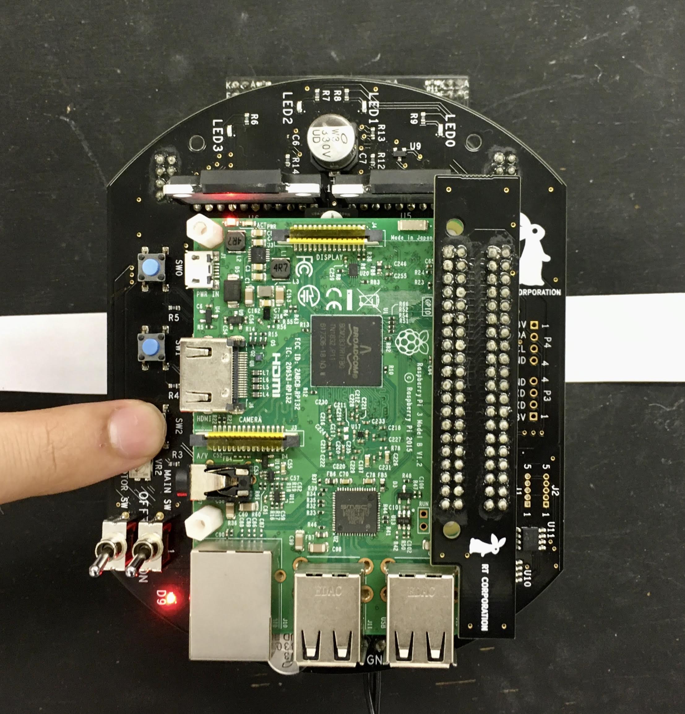
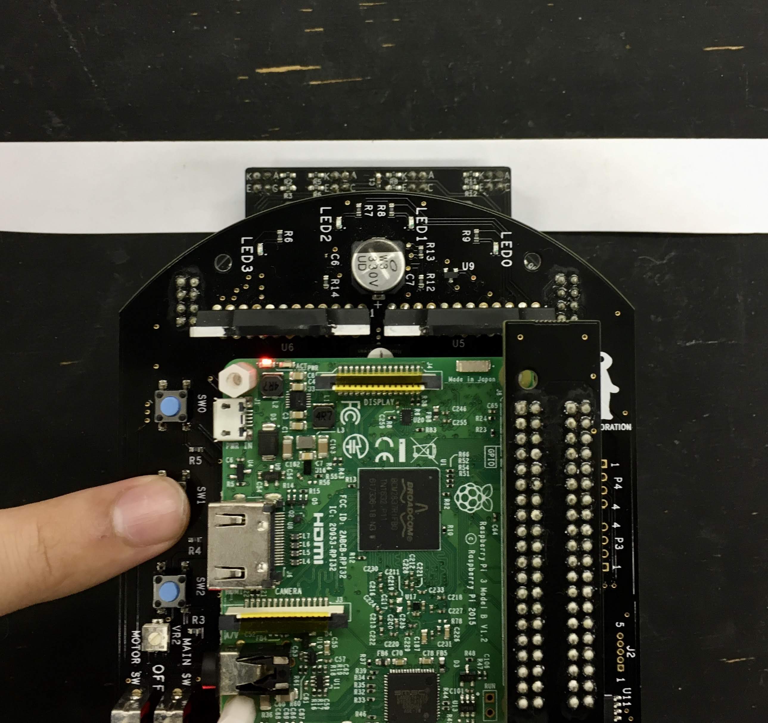
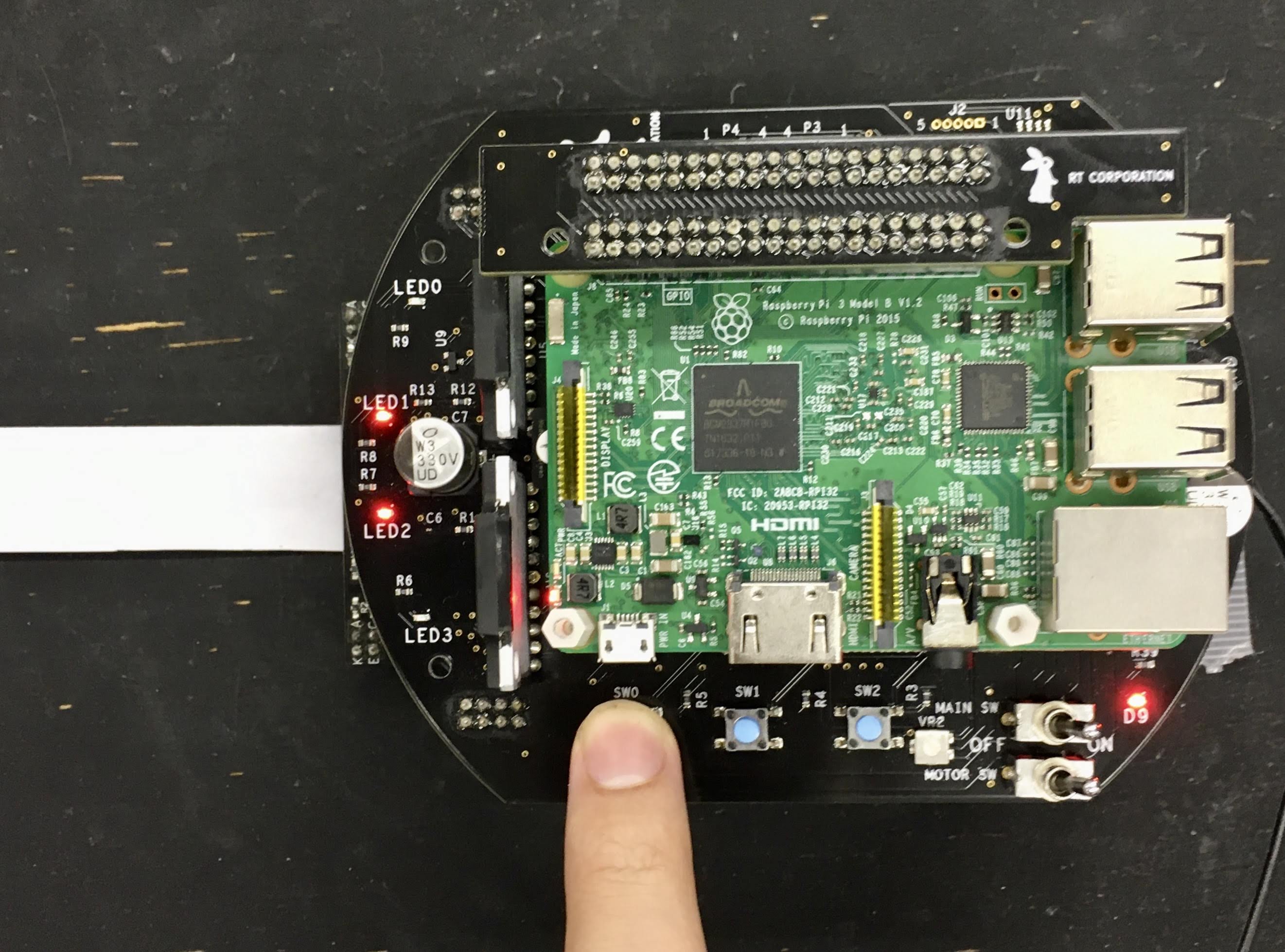
$ ros2 launch raspimouse_ros2_examples line_follower.launch.pyNext, place Raspberry Pi Mouse on a field and press SW2 to sample sensor values on the field.
Then, place Raspberry Pi Mouse to detect a line and press SW1 to sample sensor values on the line.
Last, place Raspberry Pi Mouse on the line and press SW0 to start line following.
Press SW0 again to stop the following.
Edit ./src/line_follower_component.cpp to change a velocity command.
void Follower::publish_cmdvel_for_line_following(void)
{
  const double VEL_LINEAR_X = 0.08;  // m/s
  const double VEL_ANGULAR_Z = 0.8;  // rad/s
const double LOW_VEL_ANGULAR_Z = 0.5; // rad/sThis is an example for line following by RGB camera.
- Web camera
- Camera mount
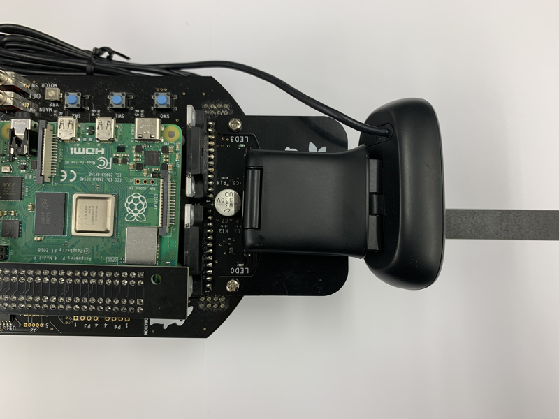
Install a camera mount and a web camera to Raspberry Pi Mouse, then connect the camera to the Raspberry Pi.
Then, launch nodes with the following command:
$ ros2 launch raspimouse_ros2_examples camera_line_follower.launch.py video_device:=/dev/video0Place Raspberry Pi Mouse on the line and press SW2 to start line following.
Press SW0 to stop the following.
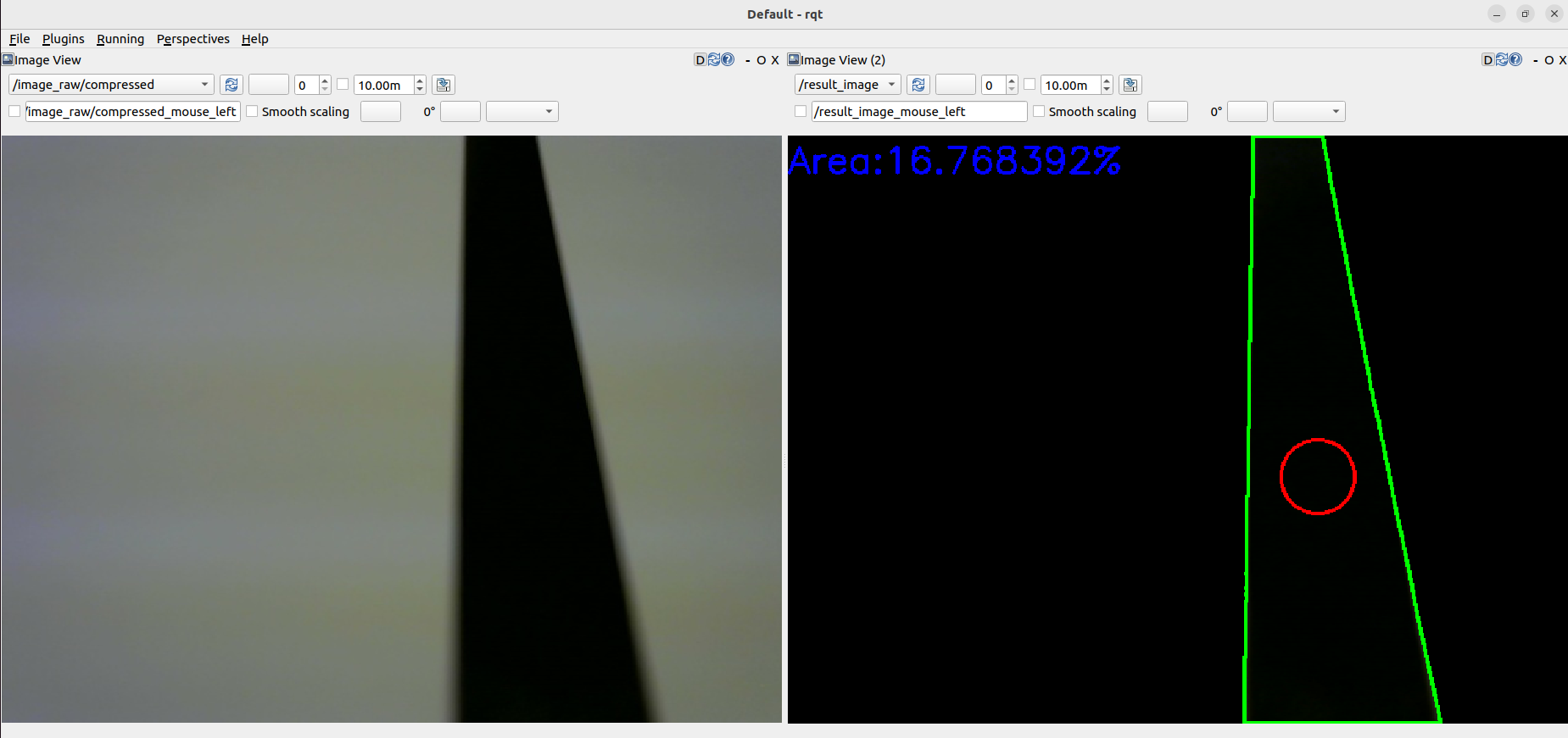
This sample publishes two topics: camera/color/image_raw for the camera image and result_image for the object detection image.
These images can be viewed with RViz
or rqt_image_view.
Viewing an image may cause the node to behave unstable and not publish cmd_vel or image topics.
If the line detection accuracy is poor, please adjust the camera's exposure and white balance.
max_brightness- Type:
int - Default: 90
- Maximum threshold value for image binarisation.
- Type:
min_brightness- Type:
int - Default: 0
- Minimum threshold value for image binarisation.
- Type:
max_linear_vel- Type:
double - Default: 0.05
- Maximum linear velocity.
- Type:
max_angular_vel- Type:
double - Default: 0.8
- Maximum angular velocity.
- Type:
area_threthold- Type:
double - Default: 0.20
- Threshold value of the area of the line to start following.
- Type:
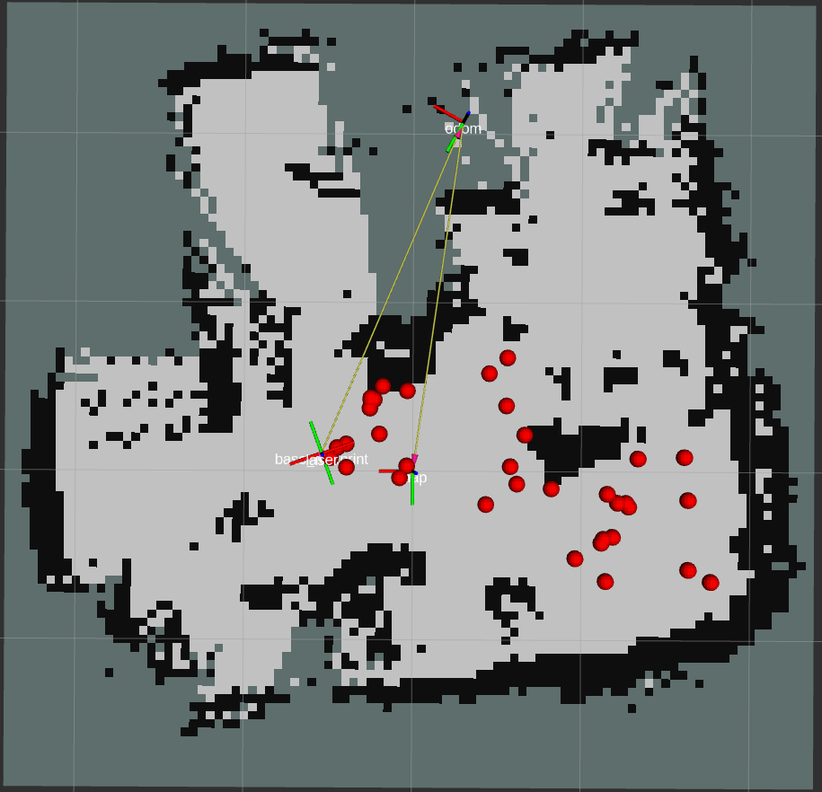
ros2 param set /camera_follower max_brightness 80SLAM and Navigation examples for Raspberry Pi Mouse is here.
This is an example to use an IMU sensor for direction control.
- USB output 9 degrees IMU sensor module
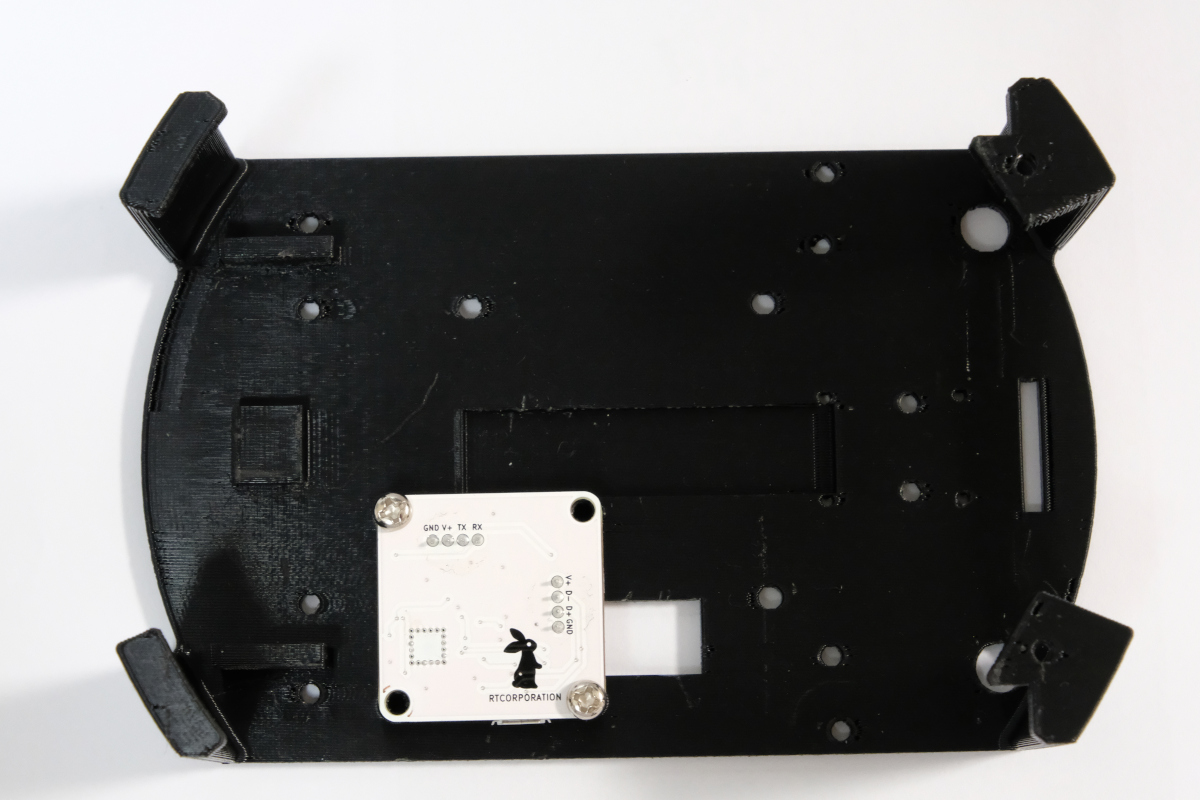
- LiDAR Mount
- RT-USB-9axisIMU ROS Package.
Install the IMU sensor module to the LiDAR mount.
Install the LiDAR mount to the Raspberry Pi Mouse.
Launch nodes on Raspberry Pi Mouse with the following command:
$ ros2 launch raspimouse_ros2_examples direction_controller.launch.pyThen, press SW0 ~ SW2 to change the control mode as following,
- SW0: Calibrate the gyroscope bias and reset a heading angle of Raspberry Pi Mouse to 0 rad.
- SW1: Start a direction control to keep the heading angle to 0 rad.
- Press SW0 ~ SW2 or tilt the body to sideways to finish the control.
- SW2: Start a direction control to change the heading angle to
-π ~ π rad.- Press SW0 ~ SW2 or tilt the body to sideways to finish the control.
The IMU might not be connected correctly. Reconnect the USB cable several times and re-execute the above command.
Set parameters to configure gains of a PID controller for the direction control.
$ ros2 param set /direction_controller p_gain 10.0
Set parameter successful

$ ros2 param set /direction_controller i_gain 0.5
Set parameter successful

$ ros2 param set /direction_controller d_gain 0.0
Set parameter successful- p_gain
- Proportional gain of a PID controller for the direction control
- default: 10.0, min:0.0, max:30.0
- type: double
- i_gain
- Integral gain of a PID controller for the direction control
- default: 0.0, min:0.0, max:5.0
- type: double
- d_gain
- Derivative gain of a PID controller for the direction control
- default: 20.0, min:0.0, max:30.0
- type: double
- target_angle
- Target angle for the SW1 control mode.
- default: 0.0, min:-π, max:+π
- type: double
- heading_angle
- Heading angle of the robot that calculated from the IMU module sensor values.
- type: std_msgs/Float64
