-
Notifications
You must be signed in to change notification settings - Fork 11
Fences
Dinosaurs can be dangerous animals. You need a way to contain and control them. You don't want them just roaming around with free will now, do you? (Electric) Fences are a great way to keep your dinosaurs (and you) safe. To make building a park easier, our fences are omni-directional and very flexible.
Arguably the most important part of anything. For these fences, the initial maths was split into two main bits.
- Raytracing - Raytracing is shooting a straight line across a grid (2d or 3d) and collecting the squares at which the line crosses.
Looking at the fences, it can be pretty obvious why raytracing was needed. I need to be able to determine which blocks are in between two different points, as to be able to place the fence cable block in those positions. After doing some research, I eventually decided on using a modified version of Bresenham's line algorithm. The algorithm is relatively simple too, compared to other algorithms I saw.
- Intersection - Intersection is pretty self explanatory. I needed to know where the line intersects a grid, as to make the rendering possible. It is also needed for the fence to have proper collision, as without knowing where the line leaves and enters the block, collision, and many other things wouldn't be possible. I ended up with using a slightly modified version of the Liang Barsky line algorithm. I had great help coding up the algorithm with this
Testing the raytracing and the intersection:


(Note that these videos are not the first iteration of code. They are a recording of the first working test of the maths logic)
Now the maths behind the fences is (somewhat) setup, its time to start placing them. As this step was practically already done, there isn't much to showcase. The next thing to do were the collisions of the fences.
Initially, I was over-thinking it, and it was harder than i thought. I tried doing a custom collision box that would detect if you were crossing it.
 Here is the basic rundown of the idea behind the custom collision box:
- Get each corner of the players collision box, and localize it to the starting intersection point
- Divide the z by the x, and compare it to the cables gradient. Store if it's smaller or bigger than the cable
- Get all 8 booleans for each point, and if they are not all equal, the box crosses the point
To the right is a line with gradient 4, and an entities bounding box, showcasing how this collision system would have worked.
However, testing it in minecraft, I found it to be too buggy to fully work. The collision box would be inconsistent, meaning that the player would rubber-band in and out of the box. If you pushed hard enough, you could even push yourself through the fence. After reconsidering things, I decided to opt for creating lots of little collision boxes instead. This change was MUCH easier than a custom box. It meant I could use Minecrafts in-built, already perfected (kinda) collision system. The logic for creating the fence collision boxes was pretty simple, and is as follows (ran individually on each block):
int amount = 16; //The amount of boxes to have per connection (in this block)
//iterate through every connection in a block
for (Connection connection : connections) {
    ConnetionIntersecion intersections = connection.intersection; //The intersections. Each component is between 0 and 1, and represents the position at which the line intersects this block
    double x = (intersections.x2 - intersections.x1) / amount; //The size of the x component per collision box
    double z = (intersections.z2 - intersections.z1) / amount; //The size of the z component per collision box

    //For i loop from 0 (inclusive) to amount (exclusive)
    for (int i = 0; i < amount; i++) {
        next = i + 1; //The next position
        boxes.append(Box.from(x*i,0,z*i).to(x*next,1,z*next).offset(intersections.x1, 0, intersections.z1)); //Creates a box from where the current is (i) to where the next one would be (next), then offsets it all by the intersection xyz1
    }
}
This lead to the very first collision working prototype (ignore the dodgy rendering):

Currently, all the maths works, but the fences cannot incline. I wasn't originally going to allow them to, as doing so would mean re-writing a huge percentage of the current code, but after some convincing, I decided to look into it.
The first thing that would need to be redone is the raytracing. First of all, I found that there were some edge cases with the current algorithm (Bresenham's line algorithm), which caused the algorithm to skip blocks, meaning the fence was (when initially placed) broken. This obviously needed to change, so, after some searching, I came across this algorithm. It seemed to be a modified version of the Bresenhams line algorithm, but done so in such a way so that it doesn't miss different blocks. Unfortunately, this algorithm also didn't fair well with inclines, so had to be redone.
Thinking about it now, I don't know why I didn't use this earlier. This was to use a heavily modified version of Minecrafts internal raytracing, the one that for sure works within Minecraft. This was easier than I thought to implement, most of hard work was figuring out what minecraft deobfuscated code meant. Once done that, I also decided to remove the Liang Barsky intersect algorithm, and replace it with another of minecrafts internal algorithms (this one also used in raytracing). The math behind the collision interpolation also had to be redone too:

Redoing this was pretty simple:
int amount = 16; //The amount of boxes to have per connection (in this block)
//iterate through every connection in a block
for (Connction connection : connections) {
    ConnetionIntersecion intersections = connection.intersection; //The intersections. Each component is between 0 and 1, and represents the position at which the line intersects this block
    double x = (intersections.x2 - intersections.x1) / amount; //The size of the x component per collision box
    double y = (intersections.y2 - intersections.y1) / amount; //The size of the y component per collision box
    double z = (intersections.z2 - intersections.z1) / amount; //The size of the z component per collision box

    //For i loop from 0 (inclusive) to amount (exclusive)
    for (int i = 0; i < amount; i++) {
        next = i + 1; //The next position
        boxes.append(Box.from(x*i,y*i,z*i).to(x*next,y*next,z*next).offset(intersections.x1, intersections.y1, intersections.z1)); //Creates a box from where the current is (i) to where the next one would be (next), then offsets it all by the intersection xyz1
    }
}
After many iterations of code and trial and erroring, I finally got math that worked with inclines.

On the scale of importance, after maths, it's rendering (in my opinion). You can do as much cool maths as you like, if the fence doesn't look cool, then less people will be attracted to it. Rendering the fences in a way I was happy with took a while, however I did eventually settle on something I was happy with.
The first step of the rendering was getting it to work without inclines, only on the x and z axis. This was relatively simple, and required some simple vector math. The diagram below shows how you would go about getting the position of one of the corner points for the fence rendering.

This all gives out the following:

The next step was to texture the cables. This was pretty easy to do, i got a texture with a random spread of gray pixels, and set the start uv to a random point in that texture. I then got the length of the intersection, and used that to set the uv correctly. This resulted in:


Now as you can see in the video and photos, the cubes cables are rendering correctly on the x and z axis, but vertically, the ends are always straight, not perpendicular to the cable direction. To fix this, I just reimplemented the math linked above, but changed x to the xz plane, and changed z to y.This gave me the following.

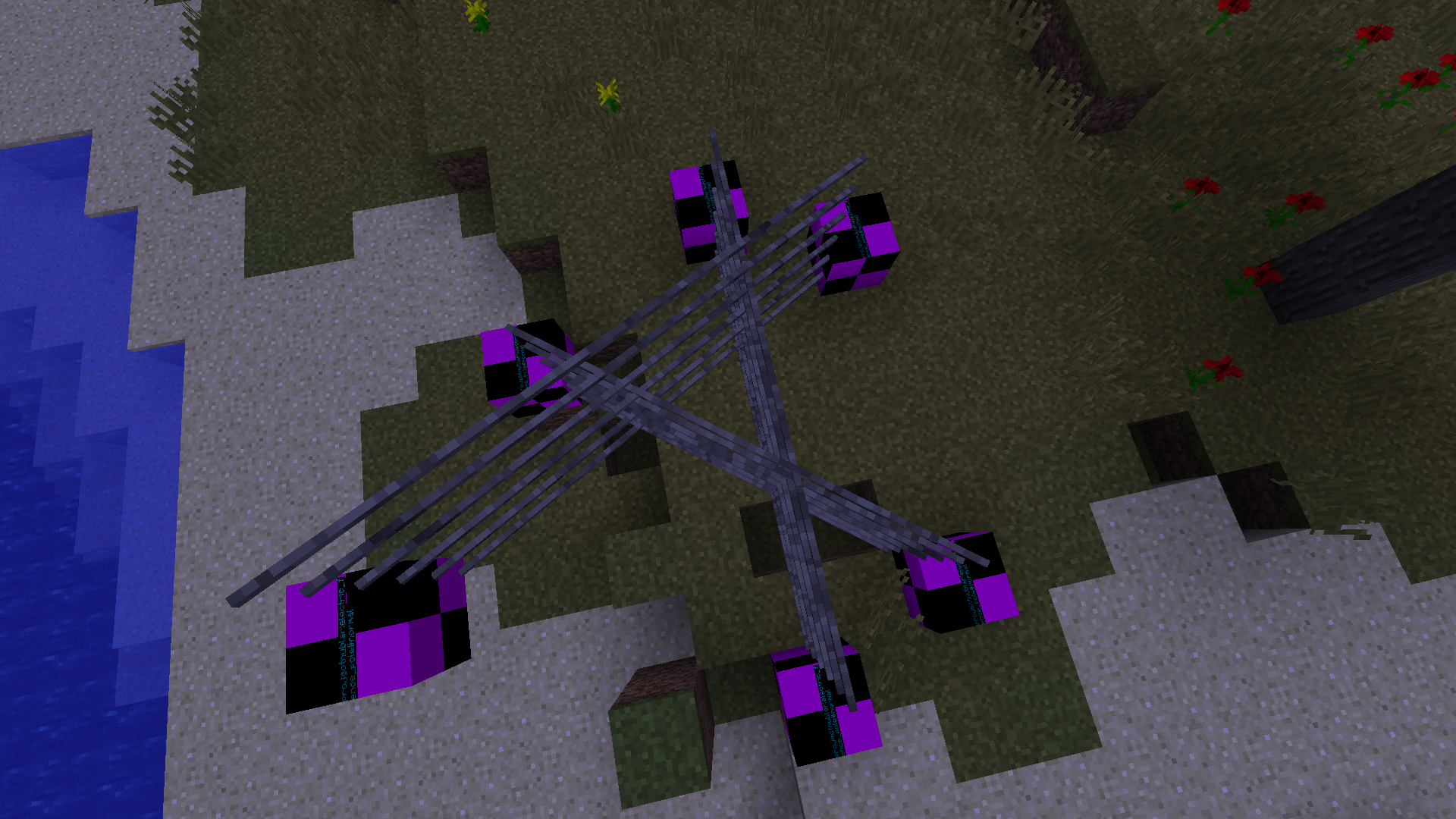
Next, I started on having the pole render. This was pretty easy to set up code wise. While I had been coding the fence cables, DumbCode's modelers (mainly kash) were hard at work creating the model for the fence poles. Once created, I was able to just render the model from the base fence block, resulting in:
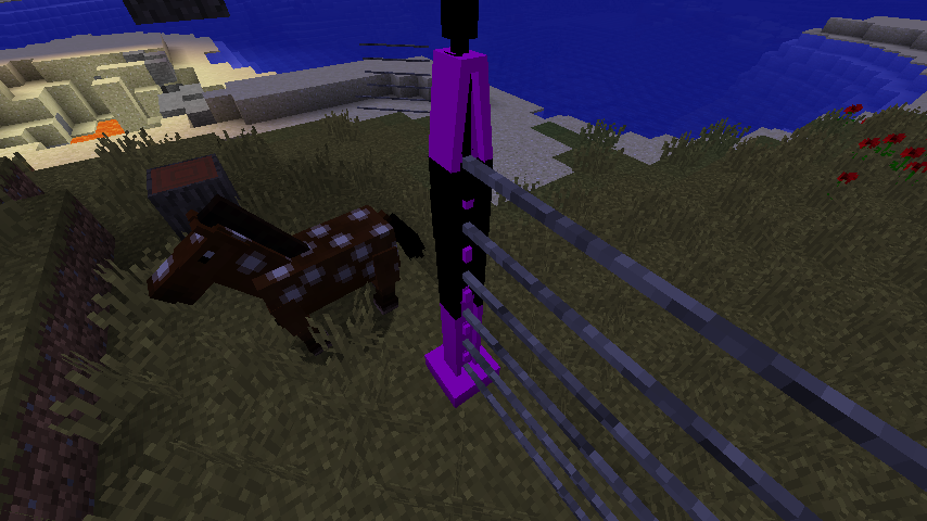
Note that this fence model is old, and at the time of screen-shotting this, a new model was already in the works. But while I waited, I worked on the pole rotations.
The pole rotation logic is pretty simple. Get the list of all cable connections to that pole. If there is only 1 connection then rotate the pole by the arctan of the fences gradient (on the x-z plane, the incline does not make a difference to the rotation) plus 90°. If there is more than one connection, get the first 2 connections and the arctan for each connection. Then, simply get the angle in between the two artans. This can be defined by the following:
float rotation = 0;
if (connections.size() == 1) {
    Connection con = connections.get(0);
    rotation = (float) Math.toDegrees(Math.atan((con.z2 - con.z1) / (con.x2 - con.x1))) + 90F;
} else if(!connections.isEmpty()) {
    Connection con1 = connections.get(0);
    Connection con2 = connections.get(1);

    double angle1 = Math.toDegrees(Math.atan((con1.z2 - con1.z1) / (con1.x2 - con1.x1))); //Note that if `con1.x2 - con1.x1` is negative, you will need to + 180° to the angle
    double angle2 = Math.toDegrees(Math.atan((con2.z2 - con2.z1) / (con2.x2 - con2.x1))); //Note that if `con2.x2 - con2.x1` is negative, you will need to + 180° to the angle

    rotation = (float) (angle1 + (angle2-angle1)/2D);
}
This (and the new model) results in:

As you can see in that gif, you are able to right click to rotate the fence pole by 180°. This is due to the way the math works, and logically it makes sense. There is no way for me to know which way around the fence should be. Example, there is no way to tell which way around these fences should go:
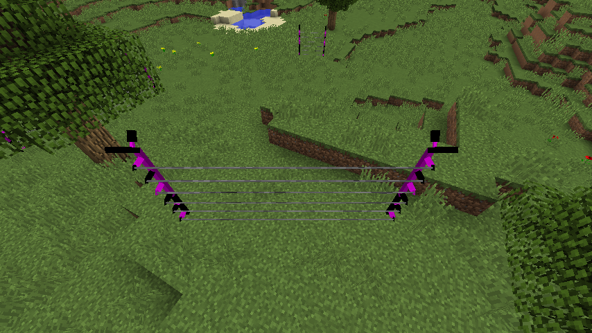
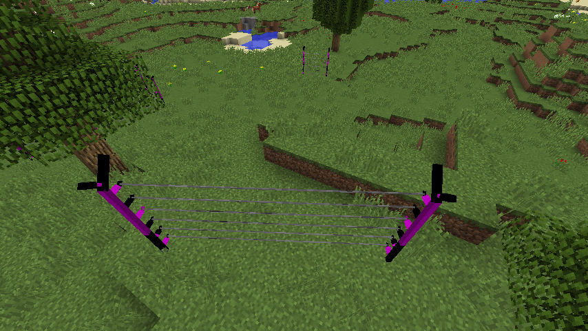
For fences with 2+ connections, the same issue applies, so allowing the user to right click to rotate 180° is the best option.
I then left town to visit family over Christmas, meaning I was unable to work on the fences. Our texture artists however, were, and were able to texture the fence pole into what it is now (credit goes to the wonderful NeusFear):

The next thing that I wanted to do was the player raytracing. Similar to the rayracing described before, player raytracing is the math behind seeing if the player is looking at a block or not. To do this, Minecraft gets where the players eyes are, and the direction the player is looking in. The Vec3 start is defined as the players end, and the Vec3 end is playerEyes.add(playerLook.scale(dist)), with "dist" being the length the player can reach.
Now, for me to be able to have rotatedr raytrace boxes, there are a few approaches. I could make my own rotated collision box, write my own collision maths, or rotate the start and end vec. My own rotated collision box is not really feasible in minecraft, as I would have to write up lots of use cases, and have to work out the maths behind it. The same issue applies to my own raytracing logic. I'd have to redo the maths behind it (most likely making mistakes). The third option however, was pretty doable.
Raytracing boxes cannot be rotated, but points in space however, can. The basic idea is to rotate the start and end positions around the first intersection. The angles to rotate at would depend on the fences rotations. I would need to rotate it so the fence becomes axis aligned, meaning the math can be done with minecrafts already working system. The gif below should explain it in more detail.
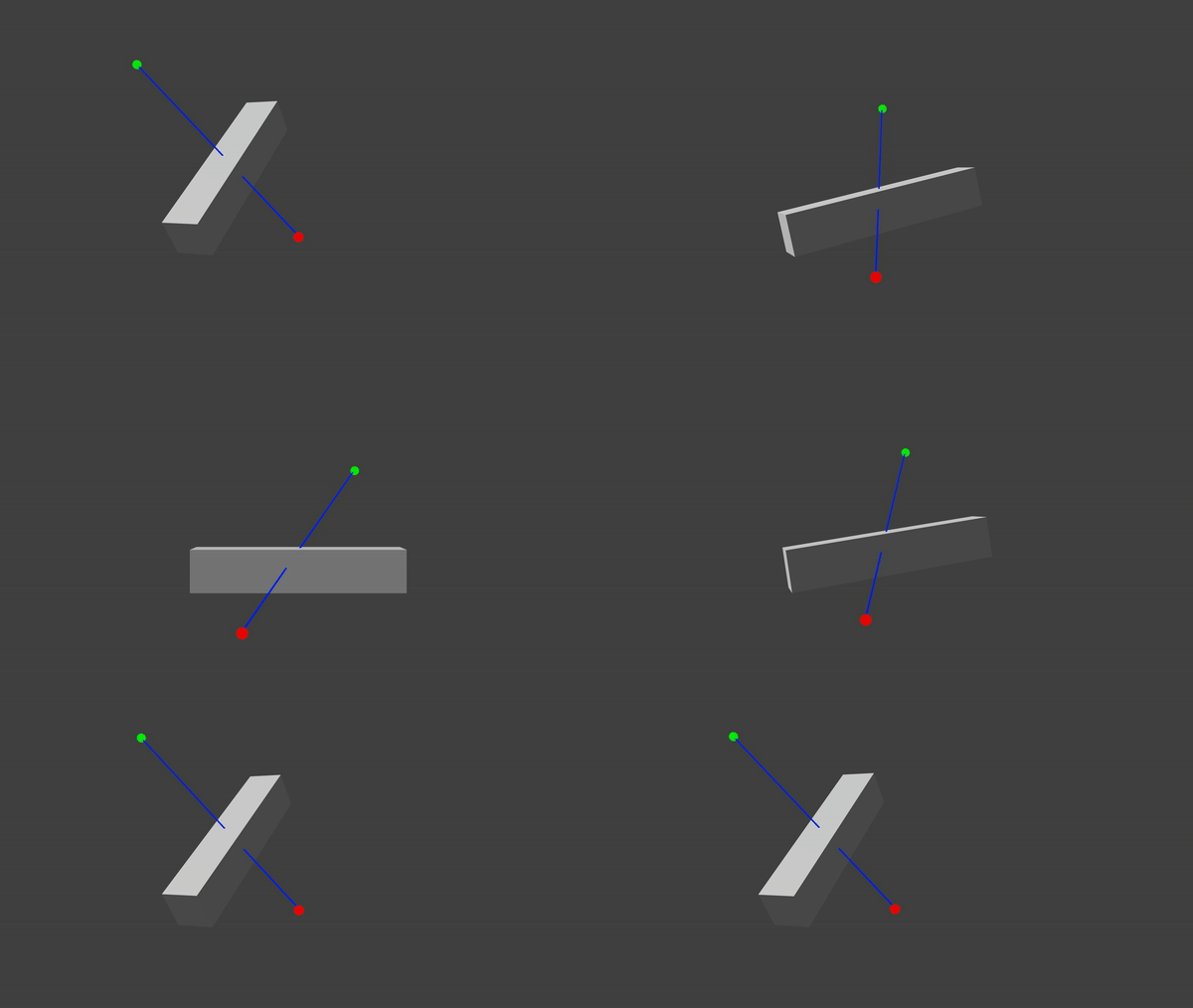
The green point represents the players eyes, and the red point represents the end vector. The blue line is the ray fired. The cube represents an intersection of the cable. The cube is rotating from the normal rotated point to a rotation of (0,0,0) making it axis aligned. The cube rotating also rotates the start and end positions around the same point. This means that I can use the same maths minecraft uses (as the box is axis aligned). This all makes it so:

I also included a "debug" mode that helped me when creating the maths. What it does, is render where the player is, where they are looking and where the box is, all rotated to fit the axis:


Currently, when you break a cable, it'll break the whole block, meaning all the other cables inside that block will break. This obviously isn't ideal, especially with the fence custom raytracing. This was pretty easy to do. All I needed to do was override Block#removedByPlayer, and just break the cable that's being looked at, and return false. If all cables are broken, return true. Now, I had created another issue. Placing the cables were messed up, as minecrafts system is used to full block blocks. Fixing this was also pretty easy, I just had to hook into the RightClickBlock and override onBlockActivated, making sure the system figured out what things go where. You can see evidence of this in the "debug" mode above.
This is something I wasn't sure I would put in, but am I glad I did. The idea is that when a cable is broken, the cables around it will bend and look broken. A programmer art style concept for the fences is as follows:
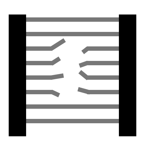
The idea is pretty simple. Get the point where the fence normally ends, rotate it some random amount on the z and x axis (assuming facing x). Then render the first half of the cable normally, and the second half with that given point as an offset. This was pretty effective and worked very nicely. First, I had to get the maths right:


Then was getting it to work with the cables:
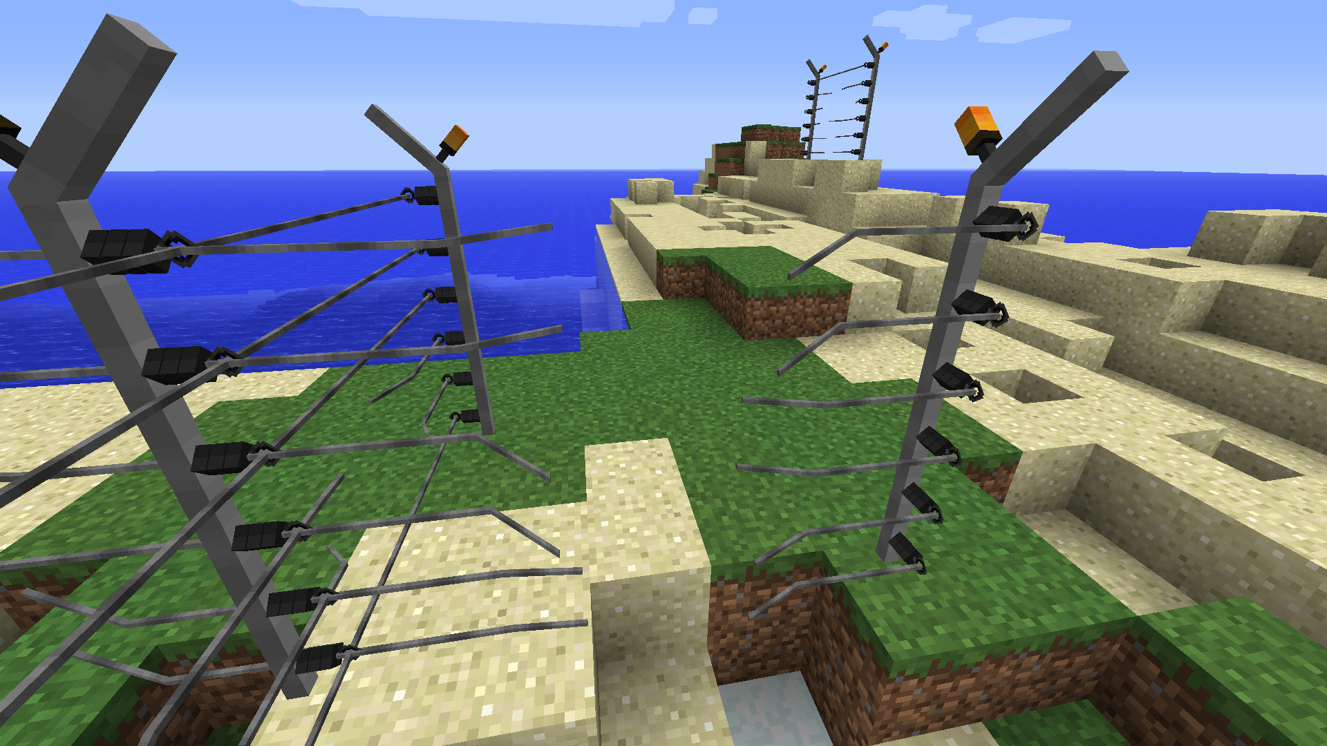
As you can see in that screenshot, cables in the same block are rotated the same way. This is because the random seed used for determining which directions the offset point goes in is based of the block position. This was easy to fix, just by incorporating the y offset of the cable into the seed creation.
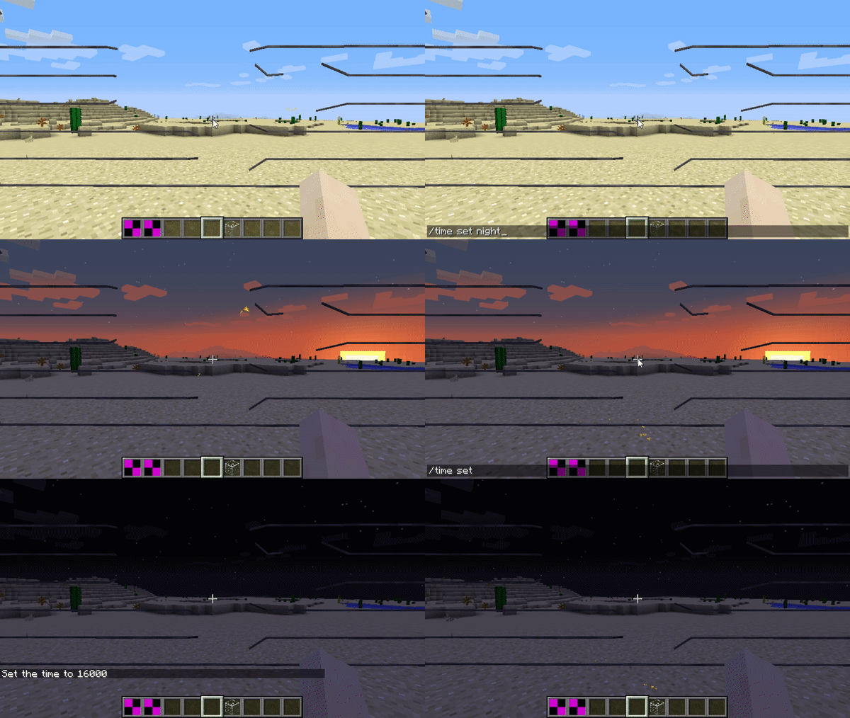
These particles would occur at broken fence points. It is meant to represents the burst of sparks you supposedly find with broken electronics. In our situation, it's meant to represent exposed wires. These were kinda easy to add. At random intervals, create a burst of particles at the cable break point plus the offset from the broken cables. The particles motion would be the normalized offset vector. I also made these particles have max lightmap light, meaning that they "glow" in the dark.
Well, thats it. Its been a wild ride making these fences, and I'm so proud and happy of the way they have turned out. I'm so happy that I was pushed out of my comfort zone multiple times, as it meant I created somthing much better than originally was planned. I hope you all like all these fences and their functionality (as well as this article). Its been so fun working on these and figuring out new things, I cant wait to show you what other things we have planned.
- Wyn Price
 Looking at the fences, it can be pretty obvious why raytracing was needed. I need to be able to determine which blocks are in between two different points, as to be able to place the fence cable block in those positions. After doing some research, I eventually decided on using a modified version of